
CHOOSE THE LOAD PATH FIRST
Coupled shaft, flange assembly, or integrated OEM shaft?
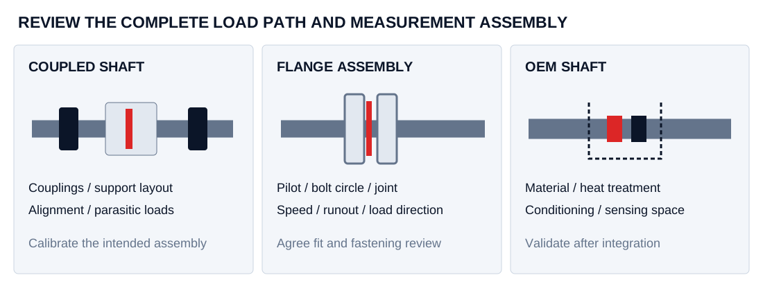
The installation format determines the drawing, support and calibration work. MSP-TRQ is a project-review family: prototype quantity, production MOQ, development scope and delivery are quoted after feasibility review.
| Route | Good starting information | Review focus |
|---|---|---|
| Coupled-shaft measurement | Coupling spacing, shaft/key/spline geometry, supports, continuous/peak torque and speed | Alignment, runout, parasitic loading and complete rotating assembly |
| Flange integration | Bolt circle, pilot, fastening and mounting envelope; load direction and transient peaks | Fit, complete joint/load path, speed capability and calibration assembly |
| OEM shaft integration | Material, heat treatment, geometry, available sensing space and magnetic environment | Conditioning feasibility, sensor gap/mounting and assembly-specific calibration |
Villari stress sensing and waveguide position measure different quantities
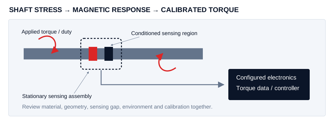
Magnetoelastic torque measurement uses stress-dependent magnetic behavior in a suitable sensing element. A stationary sensing arrangement reads the response and the calibrated electronics relate it to applied torque. The shaft material, conditioning method and mechanical/magnetic arrangement are part of that calibration.
A linear position sensor instead locates a position magnet by timing a torsional pulse along a waveguide. It is selected by stroke, measuring zones and installation geometry. Use the magnetostrictive position-sensing guide for that measurement task.
Contactless signal pickup can avoid a sliding electrical contact at the sensing interface. The full rotating assembly still needs an appropriate bearing/coupling arrangement, mechanical limits, environmental evaluation and a service plan.
Specify continuous torque, transient peaks and the usable dynamic signal
| Input | Include in the request | Why it changes selection |
|---|---|---|
| Signed torque and overload | Continuous range, short peaks, peak duration, reversals and cycle history | Measurement range and mechanical survival are different requirements |
| Rotational speed | Continuous/max rpm, acceleration, operating direction and overspeed requirement | Evaluate the entire rotating assembly and the measurement chain |
| Shaft / flange and material | Drawing, fits, grade, heat treatment, coatings, runout and available gap | Material and geometry affect the proposed magnetic sensing arrangement |
| Dynamics and accuracy | Useful bandwidth, sampling, filtering, latency, hysteresis and thermal error limits | A sampling rate or display resolution does not establish usable bandwidth or accuracy |
| Electrical integration | Receiving device, supply, analog definition or complete CAN/USB acquisition arrangement | Agree scaling, message mapping, synchronization and fault behavior |
| Environment and calibration | Temperature, oil, external fields, reference chain, load points and uncertainty target | Validate under the conditions relevant to the actual assembly |
Scroll diagram horizontally →
Test-bench transients, PTO shocks and OEM packaging need different evidence
Motor and gearbox test bench
Send both shaft interfaces, support/coupling layout and the acquisition device. Include thermal drift, reversal, acceleration and synchronization requirements alongside torque range.
Agricultural PTO driveline
Provide the shaft/spline drawing, continuous and impact loads, protective arrangement and the machine's electrical/environmental requirements. Nominal torque alone does not describe the duty.
E-mobility OEM integration
Define the sensing space, material/heat treatment, temperature, external magnetic environment and intended control function. Prototype evaluation needs an agreed calibration and validation plan.
Illustrative review scenarios. Named customer outcomes, vehicle approvals and measured MSP performance require separate evidence.
Agree shaft evaluation, reference calibration and acceptance before production
- Drawing and material review. Identify the complete shaft/flange assembly, interfaces, operating duty and intended measurement function.
- Prototype scope. Agree the proposed sensing arrangement, conditioning where applicable, output definition and any development/tooling deliverables.
- Calibration plan. Define signed load points, loading/unloading, repeatability, zero return, temperature conditions and the reference uncertainty.
- Application validation. Review dynamic response, parasitic loads, electromagnetic environment and fault handling using the intended electronics and controller.
- Production proposal. Confirm sample acceptance, quantity/MOQ, traceable records, responsibilities, packaging and delivery terms.
If you are referencing NCTE 4000/5000/7000 or an existing OEM shaft design, email the exact model and drawing. Their published series data can identify the requested format; a project proposal must establish its own fit and performance.
Questions about shaft suitability, controller data and prototype quantities
Is a magnetostrictive torque sensor the same as a waveguide position sensor?
The torque measurement responds to stress-dependent magnetic behavior in a suitable shaft or sensing element. A waveguide position sensor times a torsional pulse from a position magnet. The physical measurement task, calibration and installation are different, even though both use magnetostrictive effects.
Can any existing steel shaft become a torque sensor?
Feasibility depends on material, heat treatment, geometry, magnetic conditioning, sensing arrangement and the operating environment. Supply the shaft drawing and material specification. Evaluation and calibration must cover the proposed assembly rather than assuming that steel grade alone guarantees a usable measurement.
Can you review an NCTE 4000, 5000 or 7000 reference?
Send the exact series, range, mechanical drawing, output definition and calibration requirements. These references help identify the requested integration format. Dimensional interchangeability, controller compatibility and achievable performance need a separate written review; series names do not establish equivalence.
Which output should I request for a test bench or PTO controller?
Specify the receiving device and required interface: analog current or voltage, a defined CAN message set, or a USB acquisition arrangement. Include useful bandwidth, sampling, filtering, latency, synchronization and the treatment of speed or angle channels where required. These are configuration requests subject to feasibility review.
How are prototypes, MOQ and delivery handled?
Provide prototype quantity, annual volume and the required validation schedule. The project review should separate sensor assemblies, shaft work, calibration, tooling or development costs, production MOQ and delivery terms. Quantities and dates are confirmed in a project-specific quotation.
What calibration evidence should I request?
Agree signed torque points, loading and unloading sequences, repeatability, zero return, temperature conditions and dynamic checks. Request the reference chain, uncertainty and acceptance limits for the actual assembly. Prototype validation is a separate deliverable from a generic catalogue specification.
ROTARY TORQUE OEM PROJECT
Send torque, speed and the shaft or flange drawing.
Include prototype quantity, delivery country and annual volume in the application notes. Add the material, duty and calibration context below, or mark unknown details for review.
Compare torque with linear position and liquid-level measurement
Rod-style hydraulic position sensors
Plan an in-cylinder installation around the pressure boundary, mounting thread, piston magnet and three-part measuring envelope.
Review in-cylinder rod integration ↗02 / MSP-PROProfile-style linear transducers
External aluminum profiles for injection molding, presses and machine axes, with a guided slider or a floating position magnet.
Review external aluminum profile integration ↗03 / MSP-CMPCompact and mobile hydraulic LDTs
Review separate compact in-cylinder rod and external clevis-mounted telescoping designs for agricultural and mobile hydraulic equipment.
Review compact rod / clevis integration ↗04 / MSP-LVLLiquid level and interface probes
Configure tank level, oil/water interface and temperature measurement around the actual liquid, tank geometry and installation environment.
Review rigid / flexible tank probe integration ↗MSP-SSI / DIGITAL INTERFACESSSI and industrial fieldbus LDTs
Review frame length, resolution, controller timing and legacy Profibus-DP integration for rod or profile installations.
Compare SSI / network requirements ↗MSP-DET / FLX / RED / PROJECT REVIEWDetached, flexible and redundant position sensors
Compare remote electronics, supported flexible sensing elements and independent measuring channels against the installation drawing.
Review special-format position requirements ↗MSP-TRQ / PROJECT REVIEWContactless rotary torque sensor projects
Prepare shaft or flange geometry, torque duty, speed, output and calibration requirements for an OEM feasibility review.
Review rotary torque oem requirements ↗