
START WITH THE INSTALLATION CONSTRAINT
Restricted head space, long insertion access, or independent channels?
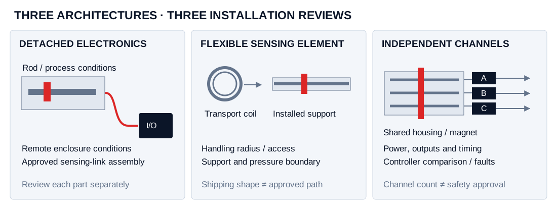
These are three distinct engineering routes. MSP-DET, MSP-FLX and MSP-RED identify project-review families; the drawing, operating conditions and required output determine the proposed assembly.
Move electronics to a serviceable location.
Useful when the cylinder head has limited space or a different thermal and vibration environment from the electronics mounting point.
Prepare rod conditions, electronics ambient, link length and the connection drawing.
Prepare a detached request ↗Plan transport and insertion as separate steps.
A flexible sensing element can change the handling plan for a long installation. Its support, permitted bends and process boundary remain part of the selected design.
Prepare active length, support drawing, access envelope and package constraints.
Prepare a flexible request ↗Define what the controller compares.
Dual or triple measurement paths support channel comparison. The complete system must define power, wiring, timing and the response to a disagreement.
Prepare channel count, each interface and the required system behavior.
Prepare a redundant request ↗Detached electronics: separate rod, cable and enclosure conditions
The sensing element and remote electronics can see very different conditions. A hot cylinder, a cooler cabinet and a cable routed near a drive each create their own requirements. Record continuous values and excursions rather than a single ambient number.
| Assembly part | Specify | Check before approval |
|---|---|---|
| Sensing rod / process seal | Fluid, continuous and peak temperature, pressure cycles, insertion drawing | Material and seal compatibility; mechanical pressure boundary |
| Remote electronics | Ambient range, mounting space, shock/vibration and ingress conditions | Enclosure configuration, service access and thermal limits |
| Sensor-to-electronics link | Assembly length, cable type, connector, shielding and routing | Approved link, permitted length and behavior at the requested interface |
| Controller/output lead | Signal definition, supply, grounding and input module | Separate the sensing link from ordinary output-cable requirements |
Temposonics RD4/RD5 names are useful original-equipment references. Send the exact code and manual revision when requesting a replacement review. A similar remote enclosure does not establish the same link cable, temperature limits or electrical behavior.
Flexible rods: verify support and access before the shipping coil
Start with the installed measuring geometry, active stroke and complete sensing-element length. Then check how the element enters and leaves its support. A low ceiling, a narrow service hatch or a rigid outer tube can govern replacement access even when the element travels in a compact package.
| Decision | Provide with the RFQ | Expected review record |
|---|---|---|
| Measuring installation | Support tube/profile, material, bore, alignment, magnet arrangement and process conditions | Installed support and pressure-boundary drawing |
| Handling and insertion | Available clearance, routing, permitted handling procedure and service withdrawal path | Model-specific bend and non-flexible section limits |
| Packaging and freight | Requested coil envelope, outer package size, destination and receiving constraints | Packaged assembly dimensions/weight and carrier quotation |
For a tank probe, also specify the liquid, floats, process opening, anchoring and hazardous-area requirements. Continue with the liquid-level probe review; a flexible position element and a float-based level assembly require different installation evidence.
Dual/triple measurement: review common points as well as separate channels
Independent electronics can still share a housing, magnet, mounting arrangement, supply source or environmental exposure. Document those common points and the controller's behavior when one channel is missing, delayed or inconsistent.
| Requirement | Define per channel / system | Approval evidence |
|---|---|---|
| Two or three measuring paths | Which paths measure independently; shared components | Block diagram and complete assembly definition |
| Power and wiring | Supply paths, connectors, grounding and cable routing | Power/fault isolation and wiring review |
| Output and timing | SSI or other defined output, scaling, update timing and synchronization | Controller configuration plus simultaneous-channel test plan |
| Comparison and failure action | Disagreement limits, timeout handling and required machine response | System validation and applicable safety documentation |
Redundancy, functional safety and hazardous-area protection answer different questions. State the intended function and required documentation in the RFQ; channel count is not a substitute for the relevant assessment. For protocol details, use the SSI and industrial-network configuration guide.
From drawing review to thermal, handling and channel validation
- Match the original installation. Supply the full model, active stroke, both blind zones, port/seal drawing, magnet and every cable assembly. Use the replacement review index for an original reference.
- Agree the proposed assembly. Request a dimensional drawing, component limits, cable/interface definition and a list of deviations.
- Define sample acceptance. The review plan should cover the complete stroke, temperature conditions, cable installation, handling/support or simultaneous-channel behavior appropriate to the architecture.
- Separate commercial deliverables. Confirm quantity, destination, drawings, validation records, packaging and delivery in the written proposal.
Hot cylinder heads, long machine axes and valve-position comparison
Restricted cylinder head
Describe the available head envelope and a proposed remote mounting location. Use detached electronics when the reviewed layout benefits from separating those environments.
Long-stroke replacement access
Show the support tube and removal route. Flexible handling can be evaluated alongside package constraints without assuming a universal stroke or bend capability.
Critical valve feedback
Define the channels the controller reads, how it compares them and what happens on a fault. Provide the system documentation requirements before selecting the assembly.
Illustrative engineering situations; no customer installation or measured performance is claimed.
Questions about remote links, flexible supports and independent outputs
How do I specify a detached sensor for a hot cylinder?
Give sensing-rod and remote-electronics temperatures separately, including peaks, dwell and start-up conditions. Add process pressure, seal materials and cable routing. An approved configuration must state limits for each part of the assembly; moving the electronics does not establish a temperature rating.
Can a flexible sensor be shipped coiled and installed directly?
Request the permitted transport bend radius, package dimensions and unpacking procedure for the selected element. Installation also needs an approved support arrangement, insertion clearance, alignment and pressure boundary. The shipping coil is a handling arrangement, not an approved measuring path.
Does a dual or triple sensor automatically provide SIL or PL capability?
Channel count alone does not establish functional-safety capability. Define independent power and signal paths, common-cause failures, controller comparison and the required fault action. Request applicable model-specific safety documentation and a system assessment for the intended function.
What is needed to review an RD4, RD5, RF or RT4 replacement?
Send the full original code, dimensional drawing, magnet details, connector definition and controller settings. Detached cable assemblies, flexible supports and redundant channel timing require individual checks in addition to stroke and thread. A written proposal should identify every difference before sample evaluation.
Can I retain the existing magnet, spacer and cable?
Provide their complete part numbers, geometry and environmental conditions. Review magnetic clearance, material behavior and sensing compatibility with the selected architecture. A generic output lead cannot substitute automatically for the sensor-to-electronics link of a detached assembly.
SPECIAL-FORMAT CONFIGURATION REVIEW
Send the installation constraint and original drawing.
Select detached, flexible or redundant below. Add the relevant thermal, support or channel context; email drawings and nameplates to [email protected].
Compare standard rod, profile and other measuring tasks
Rod-style hydraulic position sensors
Plan an in-cylinder installation around the pressure boundary, mounting thread, piston magnet and three-part measuring envelope.
Review in-cylinder rod integration ↗02 / MSP-PROProfile-style linear transducers
External aluminum profiles for injection molding, presses and machine axes, with a guided slider or a floating position magnet.
Review external aluminum profile integration ↗03 / MSP-CMPCompact and mobile hydraulic LDTs
Review separate compact in-cylinder rod and external clevis-mounted telescoping designs for agricultural and mobile hydraulic equipment.
Review compact rod / clevis integration ↗04 / MSP-LVLLiquid level and interface probes
Configure tank level, oil/water interface and temperature measurement around the actual liquid, tank geometry and installation environment.
Review rigid / flexible tank probe integration ↗MSP-SSI / DIGITAL INTERFACESSSI and industrial fieldbus LDTs
Review frame length, resolution, controller timing and legacy Profibus-DP integration for rod or profile installations.
Compare SSI / network requirements ↗MSP-DET / FLX / RED / PROJECT REVIEWDetached, flexible and redundant position sensors
Compare remote electronics, supported flexible sensing elements and independent measuring channels against the installation drawing.
Review special-format position requirements ↗MSP-TRQ / PROJECT REVIEWContactless rotary torque sensor projects
Prepare shaft or flange geometry, torque duty, speed, output and calibration requirements for an OEM feasibility review.
Review rotary torque oem requirements ↗